Electron Pi
My notebook on Raspberry Pi and Arduino projects
Monthly Archives: July 2013
DAC Shieldlet
Posted by on July 9, 2013
I made a – for want of a better word – a shieldlet.
This is the DAC from the previous post. First – it wasn’t meant to go over the top of the Arduino like that, but rather to stick out to the side. However, I made a mistake when thinking about which way round things went. Second – the output pin in the centre of the board is a bit unconventional – I put a blob of solder on the board, and stuck a header pin on top – I think I had to re-warm the solder once or twice, I definitely melted the plastic a little. Ideally I’d want a socket rather than a pin, but I didn’t have any sockets handy. Third – it’s a real pain trying to tell brown from red on those resistors! Fortunately they gave the 20k resistors thick bands, and the 10k resistors thin ones. Last – it works! I soldered it up and it works! It actually gives the voltages I wanted it to! Now I have two DACs!
Resistor Ladder DAC
Posted by on July 8, 2013
Rather than draw a circuit I’ll simply link to the wikipedia page for R-2R ladders and work with that. I bought some 10k and 20k metal film resistors from Bitsbox, ten of each, so that’s 80 pence of resistor I have to play with. Apparently these are rated to 1% tolerance. So I built some R-2R DACs, and fed the output to A0. I wrote a bit of code and put it in GitHub here. R-2R ladders still seem a little odd – how the least significant bits can have such a small effect on the output despite being connected via a small run of resistors, but I suppose it’s yet another case of “0” not being “inactive” but “a voltage sink”. I’m sure that if I thought more about Thevenin equivalent circuits I’d understand better.
So, how do the R-2R ladders do? I made a series from 3-bit to 9-bit, below, there’s a table from an experiment with a 6-bit ladder, which I think I’m sticking with.
In search of positive feedback
Posted by on July 3, 2013
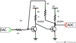
No, this doesn’t involve pandering to my audience. I had some plans last night for getting positive feedback using a single transistor, but no joy. But with two transistors, well. An obvious thing to do with an inverter is to use the output to drive another inverter; this should be a “double inverter” which converts low voltages to 0V and high voltages to 5V. Then, we can do positive feedback – take the output, attach a resistor to it, and attack the other end of the resistor back to the base of the first transistor. Schematic:
And, you know the drill by now, a graph:
No, you’re not seeing double, those really are two red lines going up. My program sweeps the DAC voltage from 0 to 5 then back to 0, and the behaviour is different on the up sweep and on the down sweep. On the up sweep, the circuit turns “on” at a bit less than 1V, on the down sweep it turns off at about 0.5v. The blue line, for comparison, is what happens without the feedback resistor. So the feedback resistor does one job; if the circuit is on, it tries to keep it on.
What you have here is something called a Schmitt trigger, closely related to a latch or a flip-flop. It’s a circuit with a memory; not only is the output voltage related to the input voltage right now, it is also related to how the input voltage was recently. This is “hysteresis” – not the sound of the crowd going wild with positive feedback for me, but a dependency on the history of the system. It’s tempting to think this is a point about the etymology of “hysteresis”, but apparently not; apparently it comes from a Greek word meaning “shortcoming”, possibly in the sense of being late.
Now I’ve seen this diagram of a flip-flop before, and it looks remarkably similar to the circuit above; basically, all you need to do is to make the circuit a bit more symmetrical. Of course, to do that, I’m going to need another DAC. But before I do that, there are other things I can make; I can use a slight variant of the circuit for LED control, I can make oscillators, there are lots of things I can try doing. As always, stay tuned.


