Electron Pi
My notebook on Raspberry Pi and Arduino projects
Feedback – an Arduino, a servo and a photocell
Posted by on November 15, 2015
Ages back I was looking at feedback loops with transistors. This time, I’m going out beyond the circuit board, and using a servo and a photocell. I thought – what’s the simplest possible feedback loop system that could be interesting? We need one sensor and one actuator. For a sensor – people seem to go for photocells (i.e. photoresistors) as a good first sensor to play with. And for an actuator – servo motors are easy to play with, if you’ve got an Arduino. So why don’t we put a photocell on a servo motor?
Of course, anything to do with this hobby involves a lot of fuss over side issues. For me, the fuss involved getting tooled up to cut a small bit of plywood to attach to the servo motor to act as a long arm. However, once all that was in place, the rest of it was fairly easy to set up. The best way to show things – video:
This started from the Knob example, which lets you control a servo motor using a potentiometer. Basically – it takes an ADC reading, scales it from 0-1023 to 0-180, and tells the servo to go to the result. High numbers represent bright light. The simplest change is to replace the “bottom half” of the potentiometer setup with a photoresistor, to give a simple voltage divider like so:

Then, run the thing. At first I tried to get it to do things by casting shadows on the photoresistor. However, I ended up finding out that shining a light on or near it worked better. Fortunately I my USB power bank has a built-in bright white LED which makes a handy torch.
So there are two sorts of feedback that can happen here. Imagine a situation where light is shining on the photocell at an angle. One way, the servo can turn the photoresistor towards the light, the other way, the servo can turn the photoresistor away from the light. The side on which the light is shining is important. On one side – as the light gets brighter, it makes the servo turn towards the light, making the light get further brighter and so on – positive feedback. On the other side, as the light gets brighter, it makes the servo turn away from the light, making the light get dimmer, making the servo turn back towards the light, and so on. One of two things can happen. Either the system reaches some sort of equilibrium, or it overshoots and oscillates. As servos can be a bit slow, we sometimes get oscillation.
As can be seen in the video, this sort-of allows for a form of light tracking – except that in some places, the system will try to keep the photocell relatively dim by pointing it at an angle to the light, and at others it will try to point it directly towards the light. After a while the system can’t find a way to be pointing towards the light, so it swings away.
So how to make a proper light tracker? Well, we could add an extra photocell, but instead, why not just change the software? Instead of letting the light level set the position of the servo, let the rate of change of light level control the rate of change of servo position. Take a reading, let the servo move in a direction, take another reading. If the reading is higher, then this looks good – keep going in that direction. Otherwise, change direction.
It took a little fiddling to get things to work properly – the main thing seemed to be that the servo needed a little time to settle into a new position between readings. However, when I’d figured that out, it seemed to be working quite nicely.
Anyway, the Arduino code is here.
So that’s about the simplest feedback system with mechanical parts I could think of. The next step? More sensors, more actuators.
Raspberry Pi Macro Photoshoot
Posted by on June 29, 2014
Long time, no post. I haven’t used my pi in a while. There were some wireless adaptor gripes – I solved those by getting another wireless USB dongle. I also got a bigger SD card and did a re-install. Getting the crucial things working – wifi, vnc, samba, all went quite smoothly.
Anyway, I got a pi camera, it sat its box unopened for the best part of a year. Then I started playing with it, did some timelapse, things like that, using my “helping third hand” thing to hold up the camera. I got a camera mount and that freed up my third hands – I already had a little tripod, and the camera mount goes reasonably well on that. It’s a bit shaky, but meh. Then I noticed you could get little lenses for cameraphones and the like, these worked with the raspberry pi, and you could get a macro lens. So I got a set from Amazon, and had a go.
First observation – the camera mount is a nice surface for sticking the little metal rings on, that the magnetic lenses attach to. I found I had to stick them on two deep for the right effect. Also, early on, the attaching rings kept coming off as I swapped lenses, but somehow that stopped being a problem.
Second observation – that little macro lens focuses very close – a few cm away – and has a very thin depth of field. There’s no autofocus, nor even manual focus. Therefore, this calls for focus-with-your-feet[1] – for moving the camera and/or subject until they’re in focus. The simplest way is to get a view of what the camera is seeing and to move the subject until in focus – this is not straightforward. With a little thought I arrived at a setup:

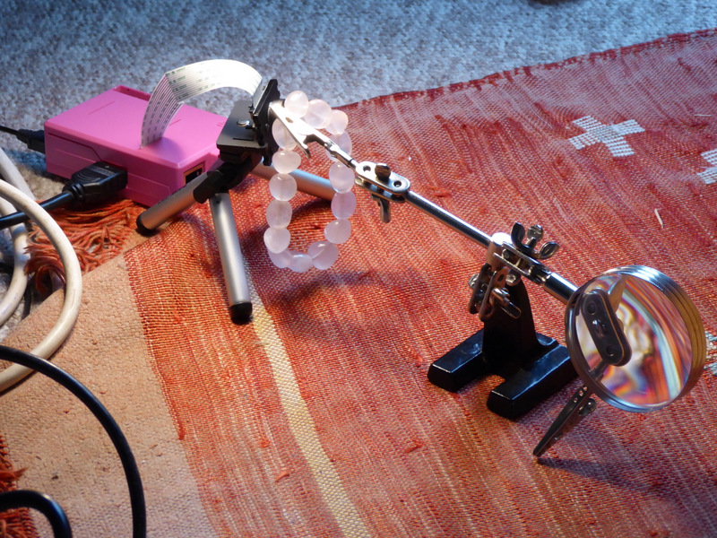
So – the pi, in the pi case, connects to the camera on a tripod. There’s also a power lead, and an HDMI cable – and a wifi dongle. Nearby we have a third hands set, and an object of interest. This gets shoved around as necessary. The HDMI cable connects to a second-hand monitor I got for pi work and never used much – alas our TV is an old CRT set and lacks HDMI. This monitor is just there as a viewfinder. The real control comes with a laptop – I ssh into the pi using PuTTY. Photographic stuff – a broken chair seat acts as a nice wooden background. Lighting is provided via big open French windows and a lamp. Also, note the bits of kitchen paper – vital for giving test items a clean before getting going, macro photography really brings out the dust and grime in things. Finally, notice the red rug. In a few photos, it was clear that light reflections off the rug added a red glow to certain parts of the scene.
Driving the camera: for stills, python in interactive mode was my friend. Having started up python, it’s simple to type in lines such as the following:
import picamera
camera = picamera.PiCamera()
camera.hflip = True
camera.vflip = True
camera.start_preview()
camera.capture("image.jpg")
And so on with variations on the last line. This worked well for still photography – once you start the preview, the preview comes up on the big screen, and stays up-to-date. What a viewfinder! I’ve peered through optical viewfinder in cheap compacts, an EVF, backs of cameras and through the eyepieces of SLRs, but this one I think is the most impressive I’ve used. Not in terms of picture quality, mind you, but for sheer wow factor it’s an experience.
Shooting video – I found the best way to do this was from bash, using raspivid. How to get your subject lined up – shoot a dummy video, that will bring the preview up, and you can Ctrl-C when you’re ready.
So what are the images like? Surprisingly good, in cases. The megapixel count is such that there’s little scope for pixel-peeping, at least not when you’re using a big modern monitor. You do need to fiddle with contrast, and especially white balance, after the event, even more so than usual. I found that the photos shot under natural light had a very cool cast to them, and the colour temperature needed to be pushed to the warm side. Anyway, there’s an album on Flickr, go have a look. A sample, apparently this is a real macro cliche but should give you an idea of the detail available:

Anyway, a great way to spend a few hours. I’m sure there’s plenty more to be done with Arduino and the Raspberry Pi in various photographic projects.
[1] Back when I was using a Canon 400D, I got a 50mm prime lens – I’d heard it described as a “zoom with your feet” lens.
DAC Shieldlet
Posted by on July 9, 2013
I made a – for want of a better word – a shieldlet.


This is the DAC from the previous post. First – it wasn’t meant to go over the top of the Arduino like that, but rather to stick out to the side. However, I made a mistake when thinking about which way round things went. Second – the output pin in the centre of the board is a bit unconventional – I put a blob of solder on the board, and stuck a header pin on top – I think I had to re-warm the solder once or twice, I definitely melted the plastic a little. Ideally I’d want a socket rather than a pin, but I didn’t have any sockets handy. Third – it’s a real pain trying to tell brown from red on those resistors! Fortunately they gave the 20k resistors thick bands, and the 10k resistors thin ones. Last – it works! I soldered it up and it works! It actually gives the voltages I wanted it to! Now I have two DACs!
Resistor Ladder DAC
Posted by on July 8, 2013
Rather than draw a circuit I’ll simply link to the wikipedia page for R-2R ladders and work with that. I bought some 10k and 20k metal film resistors from Bitsbox, ten of each, so that’s 80 pence of resistor I have to play with. Apparently these are rated to 1% tolerance. So I built some R-2R DACs, and fed the output to A0. I wrote a bit of code and put it in GitHub here. R-2R ladders still seem a little odd – how the least significant bits can have such a small effect on the output despite being connected via a small run of resistors, but I suppose it’s yet another case of “0” not being “inactive” but “a voltage sink”. I’m sure that if I thought more about Thevenin equivalent circuits I’d understand better.
So, how do the R-2R ladders do? I made a series from 3-bit to 9-bit, below, there’s a table from an experiment with a 6-bit ladder, which I think I’m sticking with.
In search of positive feedback
Posted by on July 3, 2013
No, this doesn’t involve pandering to my audience. I had some plans last night for getting positive feedback using a single transistor, but no joy. But with two transistors, well. An obvious thing to do with an inverter is to use the output to drive another inverter; this should be a “double inverter” which converts low voltages to 0V and high voltages to 5V. Then, we can do positive feedback – take the output, attach a resistor to it, and attack the other end of the resistor back to the base of the first transistor. Schematic:

And, you know the drill by now, a graph:

No, you’re not seeing double, those really are two red lines going up. My program sweeps the DAC voltage from 0 to 5 then back to 0, and the behaviour is different on the up sweep and on the down sweep. On the up sweep, the circuit turns “on” at a bit less than 1V, on the down sweep it turns off at about 0.5v. The blue line, for comparison, is what happens without the feedback resistor. So the feedback resistor does one job; if the circuit is on, it tries to keep it on.
What you have here is something called a Schmitt trigger, closely related to a latch or a flip-flop. It’s a circuit with a memory; not only is the output voltage related to the input voltage right now, it is also related to how the input voltage was recently. This is “hysteresis” – not the sound of the crowd going wild with positive feedback for me, but a dependency on the history of the system. It’s tempting to think this is a point about the etymology of “hysteresis”, but apparently not; apparently it comes from a Greek word meaning “shortcoming”, possibly in the sense of being late.
Now I’ve seen this diagram of a flip-flop before, and it looks remarkably similar to the circuit above; basically, all you need to do is to make the circuit a bit more symmetrical. Of course, to do that, I’m going to need another DAC. But before I do that, there are other things I can make; I can use a slight variant of the circuit for LED control, I can make oscillators, there are lots of things I can try doing. As always, stay tuned.
LED driving bakeoff
Posted by on June 30, 2013
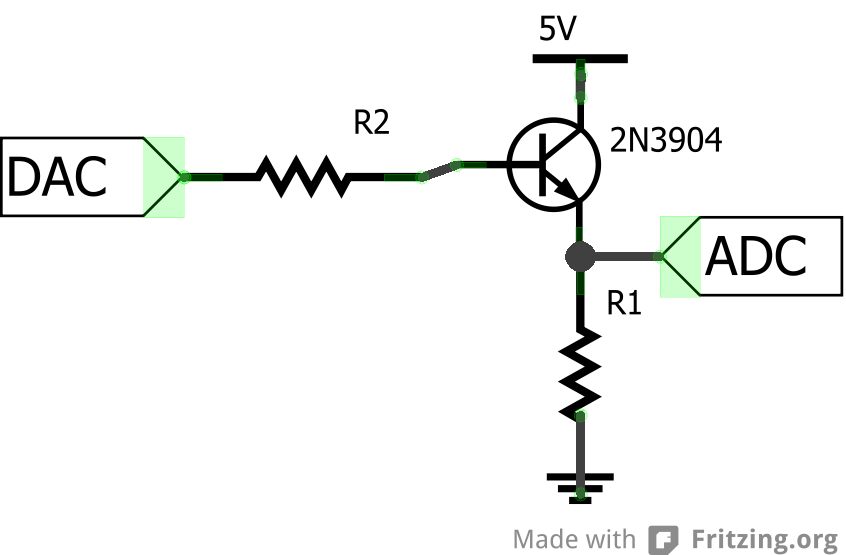
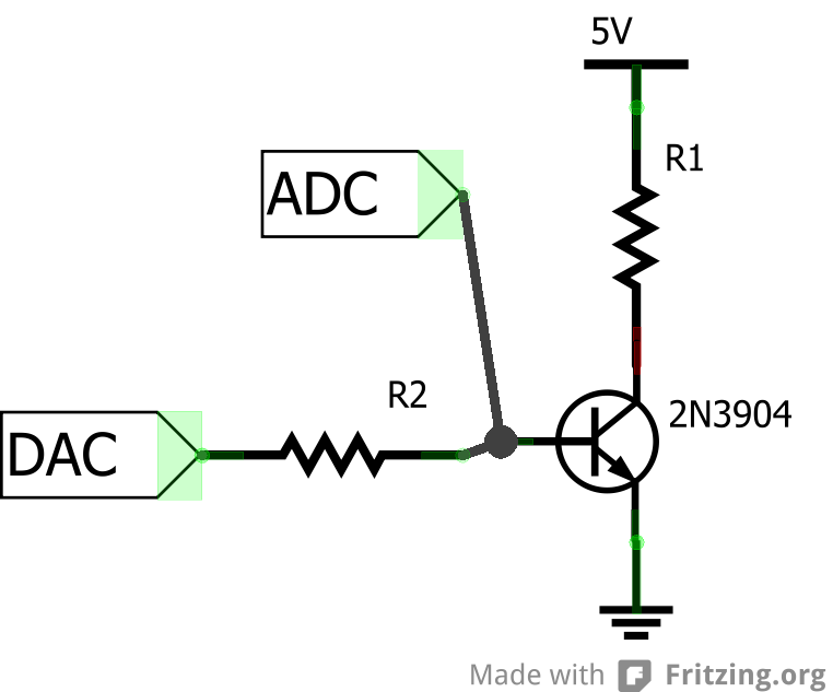
A thought – using a transistor to control an LED. There are at least two ways to do this – schematic:

Circuit 2 is basically an inverter with an LED in. One thing I’m learning – “low” or “zero” does not mean “off”, rather, “ready to sink current”. Have I made this point before? Anyway, I’ve put a 100R resistor in series with a green LED, as that’s a sensible size resistor to have there. Circuit 2 uses a different principle. In both cases I’ve placed the ADC to measure the voltage across the resistor – this lets us work out the current going through the resistor and hence the LED. The 10k resistor is there to make life difficult but not too difficult – to simulate a case where we want to work with low-current signals. Anyway, graphs:

So blue and red are the measured voltages, on the primary y-axis, and green and purple are the calculated currents – plotted on the secondary axis. The first point is that Circuit 1 wins. It seems to be easier to sink current with the collector of your transistor, than to source it with the emitter. Second – note that not only does the green line turn on earlier (at a mere 0.7V or so – compare with just driving an LED!), the curve slopes up much more sharply. Third – note how curvy the curve gets. Once the current gets near 20mA the curve starts to get nonlinear, and seems to be close to saturating a bit above 25mA, although it looks like the curve has a little way to go yet.
Of course, if we wanted steeper curves, then a Darlington pair might be a way to get that.
If one transistor is good, then two must be better
Posted by on June 29, 2013
Ah, time for a second transistor. There are lots of things we can do with a second transistor. One simple thing, in terms of keeping the resistor count low, is to build a Darlington pair. I heard about these when I heard about the ULN2803A chip, which people sometimes use for driving motors. It turns out that a Darlington pair is where you hook up the two collectors of two transistors, and the emitter of one to the base of the other. So a tiny current goes into the base of the first transistor, a medium current goes out of the emitter of the first into the base of the second, allowing a big current to flow through the third. Usually, the two transistors are on the same chip – you can get single components called Darlington transistors with three legs just like a normal discrete BJT. However, because it’s always fun to make your own, it’s schematic time:

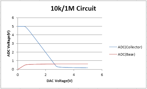
Here, I use a 1k resistor for R1 and a 1M resistor for R2. This gave a very shallow slope when I plotted a graph several posts back, using a setup similar to the one above, but with a smaller transistor. I still have the data for that graph, so let’s dig it out, and also plot a similar graph for the new setup:
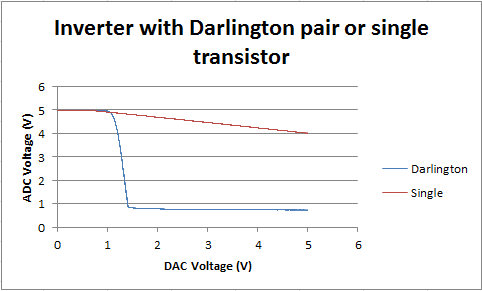
Ah yes, that seems to have more-or-less the desired effect – the inverter is now far less wimpy, and produces a nice low voltage at the ADC when the DAC voltage is turned up. There are two things of note: first, the flat bit at the top lasts for about 1.2V rather than about 0.7V. To turn the transistors on, there needs to be enough voltage at the DAC to cope with the voltage drop across two transistors, not just one. The second thing – the voltage at the ADC doesn’t bottom out at 0V, more like 0.75V. I’m not quite sure why that is. It seems, reading the wikipedia page, that this effect is expected.
Still, let’s do some maths, with some quick approximations. The current going through that 1M resistor can’t be more than 5µA, whereas the 1k resistor could well have about 4mA going through it. Possibly if we used a smaller resistor, we could get an even bigger current, and still get 4-and-a-bit volts across it. This is, of course, the big idea behind a Darlington pair – to use a small current to control a large current.
A thought – the two transistors in the Darlington pair are doing different jobs, in that with the first transistor, you care about what’s going on at the emitter, whereas with the second transistor, it’s what’s going on at the collector that’s important.
Anyway, next time I should add some more resistors. It’s not as if they are expensive…
More with a transistor and resistors
Posted by on June 28, 2013
Did I say I was finished with one transistor plus some resistors? It turns out there’s at least one last thing to try – feedback! As ever, a schematic:

So this is the inverter from a few posts ago, plus R3 and R4. Forget R4 for now – most of the graphs (how did you guess?) will be done without R4 (i.e. empty air where R4 is on the diagram). The idea of R3 is negative feedback. Simply: imagine R3 wasn’t there, and the DAC was at low voltage. The inverter would be “on” – i.e. there would be a high voltage at the ADC. Then put R3 in – this would mean that current could go through R3 to the base of the transistor, switching the transistor on, thus dropping the voltage at the transistor, and thus meaning that there’s less scope for current through R3. So R3 doesn’t switch the transistor on… wait a moment… what this means it that the system will reach an equilibrium whereby the transistor is on but not saturated, and lets some current through, but not too much. Then, varying the DAC voltage should gently alter this. OK, some graphs. I’ve used slightly different settings to try and make things a bit clearer:
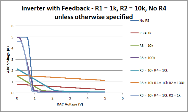
OK, that’s complicated. You might recognise the navy blue line, “No R3”, which shows the behaviour of an inverter without R3. If we put in a 1k resistor at R3, we get the red line. 10k gives us green, 100k gives us dark violet. Interesting point: all four of these lines so far go through the same point, at about 1V on the DAC, 0.7 or so on the ADC. So, as expected, adding R3 has lowered the voltage at the ADC at low DAC voltages. The slope is more shallow. Also, without R3, it takes about 0.7V of DAC voltage to turn the transistor on – with R3, we seem to be past that already. At high DAC voltage, the circuit seems to give a higher ADC voltage than without R3 – maybe current is flowing along R3 the other way at those voltages.
Adding R4 to the circuit that gives the green line, gives the greenish-blue line. It’s like using R3 and R4 as a voltage divider, to get a bias point, or something like it. Finally, there’s the orange line, and the pale violet line, which come from adjusting R2. It’s interesting how the orange line is like the red line, shifted upwards.
Anyway, this circuit is starting to look like some of the amplifier circuits I saw when I was investigating electret microphones. If I recall right, there should be a resistor from the emitter to ground, and a capacitor where R2 is – also a capacitor from the emitter to ground maybe??? At any rate, I’m starting to understand what’s going on here – I’m also starting to understand why a friend of mine said that op-amps were the way forward.
So that’s negative feedback (i.e. what this blog post deserves – ed.) – what about positive feeback? I don’t think you can do that with a single transistor. But with two, yes, it should be pretty easy – just take the output from transistor A, use transistor B in an inverter, then feed that back to transistor A. Stay tuned.
Following on from the inverter
Posted by on June 27, 2013
There’s an obvious variant of the inverter to think about: what if there wasn’t a resistor from the collector to 5V, and instead a resistor from the emitter to ground. In other “words”:
As before: the transistor acts a bit like a diode… so once the DAC voltage gets high enough, there should be a constant voltage drop between the base and emitter. If the transistor can send as much current through the collector pin as R1 will take, then the voltage at the ADC should be the DAC voltage, minus the turn-on voltage for the transistor. Apparently this arrangement is called a “voltage follower”, it lets you have a voltage with a small current one side of the transistor, and that voltage (minus half a volt or so) at higher current on the other side. Let’s plot a graph:

So the green line is what we expect. The red line is more-or-less what we expect. With the blue line – the resistor R2 is so resistive, that the current going to the base pin is going to be small… likewise, the resistance is so high that there might be an appreciable voltage across R2. Either way, we’re not getting the nice voltage-following behaviour we might have hoped for. Nevertheless, if you compare and contrast with the experiments with the inverter, then those three lines are a lot closer than their counterparts in the inverter circuit.
So that’s probably enough with one transistor and some resistors for now. Maybe we could add another transistor, or a diode (an LED, maybe) or something else, see what we can get it to do. Next post maybe.
More on that inverter
Posted by on June 26, 2013
I decided to try moving the ADC, to look at the voltage next to the base of the transistor, rather than next to the collector:
If I choose R1 as 10k and R2 as 1M, and also include the readings from the collector (see the circuit diagram in the previous post), then I get the following graph:
This is all starting to make sense – between my experiments and what I’ve read, I’m starting to get a feeling for what’s going on. Between the base and the emitter, the transistor acts like a diode – a bit like the LED I plotted a graph for – except that the current flowing base-to-emitter also controls the current flowing collector-to-emitter.
Now the challenge is voltage amplification. I can make the ADC voltage go down steeply when the DAC voltage goes up. But what’s the simplest way to make the ADC voltage go up steeply when the DAC voltage goes up. Given that the voltage at the base is going to be higher than the voltage at the emitter, we’re going to have to think about the voltage at the collector. Possibly this entails another transistor, or maybe some clever tricks with resistors. Or I could even stray a bit from the beaten path and try to understand PNP resistors. Absolutely doubtless there’s a nice canned solution somewhere waiting for me to just look up, but figuring it out is more fun.
